
Part Nine: Layer 2 Switching Fundamentals
The topic
Layer 2 is where devices on the same local network actually talk to each other. At this layer, devices are identified not by IP address but by MAC address, a unique hardware identifier burned into every network interface. A switch is the device that connects everything on a local segment together, and its core job is simple to state: learn which MAC address lives on which port, and forward each frame only to the port where its destination lives.
A switch builds a MAC address table by watching the source addresses of frames as they arrive. Once it knows that device A is on port 3, it sends traffic for A only to port 3, instead of flooding it everywhere. This is the fundamental difference between a switch and the ancient hub it replaced: a switch creates a separate collision domain per port and forwards intelligently.
How it is generally implemented
A switch works out of the box at Layer 2 with no configuration, learning MACs and forwarding frames automatically. Configuration enters when you want to segment traffic (VLANs), control which devices may connect (port security and 802.1X), provide loop protection (spanning tree), or combine ports for more bandwidth (link aggregation). These are the topics that follow.
Why it matters
Most “weird” local network problems are Layer 2 problems: a duplicate MAC, a full MAC table, a misconfigured port, a loop. Because Layer 2 has no concept of a “time to live” the way Layer 3 does, a single cabling loop can melt an entire network in seconds as frames multiply endlessly. Understanding Layer 2 is what separates an engineer who can fix a flaky office network from one who can only reboot it.
In an SD-WAN world
SD-WAN is fundamentally a Layer 3 (and above) technology, it routes between sites, but one of SpeedFusion’s most powerful tricks is the ability to extend Layer 2 across the wide area. With a Layer 2 SpeedFusion tunnel, two physically distant sites, or hundreds of mobile units, can behave as if they are on the same local switch, sharing one seamless network. This is the foundation of the roaming, infrastructure-less wireless networks West Networks builds for large mobile sites, where devices move across a huge area but stay on one continuous Layer 2 network.
Part Ten: VLANs, Trunks, Access Ports, and the Vocabulary That Confuses Everyone
The topic
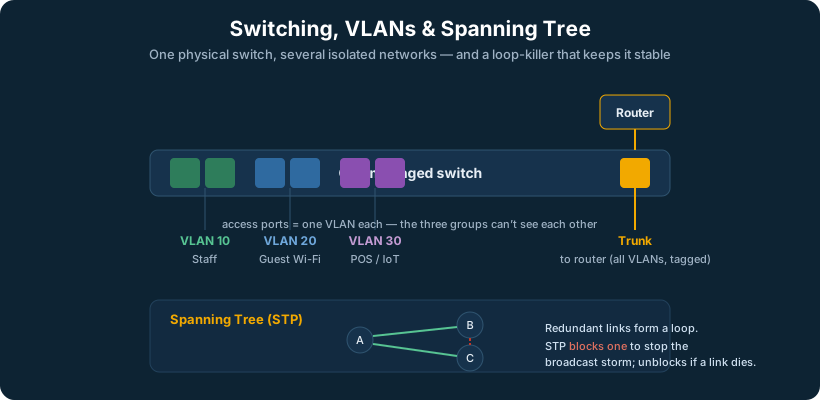
A VLAN (Virtual LAN) lets one physical switch behave as several separate logical switches. Traffic in VLAN 10 cannot reach VLAN 20 without passing through a router or Layer 3 device, even though both might live on the same physical switch. This is how a single piece of hardware separates staff from guests, payment systems from cameras, and corporate data from IoT.
Here is the vocabulary that trips people up, laid out plainly:
- An access port carries traffic for exactly one VLAN. You plug an end device, a PC, a printer, a camera, into an access port, and that device lives in that one VLAN, unaware that VLANs even exist.
- A trunk port carries traffic for many VLANs at once, over a single link. You use a trunk between two switches, or between a switch and a router or firewall, so that all the VLANs can travel across one cable. Trunks keep traffic separated by adding a small VLAN tag (the 802.1Q standard) to each frame, stamping it with which VLAN it belongs to.
- The PVID (Port VLAN ID) is the VLAN assigned to untagged traffic arriving on a port. On an access port, the PVID is simply that port’s VLAN.
- The native VLAN is the one VLAN on a trunk whose traffic is sent untagged. By convention it exists for legacy compatibility, and by security best practice you change it away from the default (VLAN 1) and never put real user traffic on it.
The 802.1Q VLAN ID ranges
| VLAN ID | Status | Notes |
|---|---|---|
| 0 | Reserved | Used for 802.1p priority tagging only, not a real VLAN |
| 1 | Default | Every port starts here; best practice is to NOT use it for real traffic |
| 2 – 1001 | Normal range | Your everyday usable VLANs |
| 1002 – 1005 | Reserved | Legacy Token Ring / FDDI (Cisco), leave alone |
| 1006 – 4094 | Extended range | Available on modern switches for large deployments |
| 4095 | Reserved | Not usable |
That gives 4,094 usable VLANs total, which is the practical ceiling of plain 802.1Q and one reason very large multi-tenant networks reach for newer technologies like VXLAN.
Access port vs. trunk port at a glance
| Access port | Trunk port | |
|---|---|---|
| VLANs carried | Exactly one | Many (a defined allowed list) |
| Tagging | Untagged to the device | 802.1Q tagged (except the native VLAN) |
| Connects to | End devices (PC, printer, camera, AP) | Other switches, routers, firewalls |
| Key setting | PVID = the access VLAN | Native VLAN + allowed VLAN list |
| If misconfigured | Device lands in the wrong VLAN | VLAN leakage, or VLANs simply do not pass |
How it is generally implemented: subnetting, VLANs, and inter-VLAN routing as one design
These three topics are taught separately but in practice they are a single design exercise. A VLAN is a Layer 2 broadcast domain; a subnet is a Layer 3 address range; in a well-built network they map one-to-one, one VLAN equals one subnet, and a router or Layer 3 switch ties them together. Getting this mapping clean is the core skill of network design, so here it is end to end.
Step one: design the VLAN and subnet plan together. Decide the segments the site needs (by function and by security boundary), give each a VLAN ID and a matching subnet, and write it down as one table. A clean convention many engineers use is to make the third octet match the VLAN ID, so VLAN 20 is 10.0.20.0/24, which makes the whole network self-documenting.
A worked example: a mid-size clinic
| Purpose | VLAN | Subnet | Gateway | Usable hosts | Notes |
|---|---|---|---|---|---|
| Management (switches, APs) | 10 | 10.0.10.0/24 | 10.0.10.1 | 254 | Restrict tightly; admin access only |
| Staff workstations | 20 | 10.0.20.0/24 | 10.0.20.1 | 254 | Standard user VLAN |
| Clinical / EHR devices | 30 | 10.0.30.0/24 | 10.0.30.1 | 254 | Isolated for compliance |
| Medical imaging | 40 | 10.0.40.0/23 | 10.0.40.1 | 510 | Larger; big files, more devices |
| VoIP phones | 50 | 10.0.50.0/24 | 10.0.50.1 | 254 | Voice VLAN, prioritized in QoS |
| Security cameras / IoT | 60 | 10.0.60.0/24 | 10.0.60.1 | 254 | No internet, no access to other VLANs |
| Guest Wi-Fi | 70 | 10.0.70.0/24 | 10.0.70.1 | 254 | Internet only, fully isolated |
| Point-to-point to edge | 99 | 10.0.99.0/30 | — | 2 | Router-to-firewall link |
Step two: configure the switch ports. Each end device sits on an access port set to its VLAN (a clinical PC on an access port with PVID 30). The links between switches, and the link up to the router or firewall, are trunks carrying the VLANs that need to travel. Set the native VLAN on those trunks to an unused, parked VLAN (never VLAN 1, never a user VLAN) and explicitly list the allowed VLANs.
Step three: route between the VLANs. By design, VLAN 20 cannot talk to VLAN 30 on its own, that is the whole point of separating them. Anything that needs to cross VLANs goes through a Layer 3 device, and there are two classic ways to do it:
- Router on a stick: a single trunk from the switch to a router, with the router holding a “subinterface” (a virtual interface with an IP) for each VLAN, acting as the gateway for each subnet. Simple and cheap; the single trunk can be a bottleneck at large scale.
- Layer 3 switch (SVIs): the switch itself does the routing, with a Switched Virtual Interface per VLAN serving as that subnet’s gateway. Faster, the standard for any sizable site, and the function the traditional core switch performed.
Either way, the gateway addresses in the table above (the .1 of each subnet) live on that Layer 3 device. A device sends anything destined for another subnet to its gateway, the Layer 3 device routes it to the destination VLAN, and your firewall rules decide which of those crossings are actually allowed (guest to staff: denied; staff to imaging: permitted; cameras to anything: denied).
Why it matters
VLANs are where network design, performance, and security meet, and the subnet-to-VLAN mapping is where an abstract address plan becomes an enforceable security policy. They contain broadcast traffic, they isolate sensitive systems, and they are the boundaries your firewall rules depend on. Nearly every compliance requirement, PCI for payment systems, segmentation for medical devices, guest isolation, is implemented with this VLAN-and-subnet structure at its foundation. You cannot write the rule “guests cannot reach clinical devices” until guests and clinical devices live in different VLANs and subnets; once they do, the rule writes itself.
What you actually see in the GUI/CLI: access vs. trunk. On a switch interface, an access port is configured with a single VLAN (in a web GUI, a dropdown like “VLAN: 30, Untagged”; in Cisco-style CLI, switchport mode access and switchport access vlan 30). A trunk port shows a list of allowed VLANs and a designated native VLAN (in a GUI, a grid of VLANs each marked tagged/untagged; in CLI, switchport mode trunk, switchport trunk native vlan 99, switchport trunk allowed vlan 10,20,30). The quick tell: an access port names one VLAN as untagged; a trunk names many VLANs as tagged plus one untagged native.
Which VLANs to carry on which trunks, allow all, or be selective? Be selective. Only carry on a trunk the VLANs that actually need to reach the device on the other end. This is called VLAN pruning, and it matters for two reasons: it limits broadcast traffic to where it is needed, and it shrinks the attack surface (a VLAN that is not on a trunk cannot be reached through it). In the clinic example, the trunk up to the edge device carries every VLAN that needs to route or reach the internet, but a trunk to a switch that only serves exam rooms might carry just staff, clinical, and voice, not guest or cameras. “Allow all VLANs on every trunk” is the lazy default that works until it causes a broadcast or security problem; deliberate pruning is the professional habit.
Why changing the native VLAN off 1 matters, and what goes wrong if you don’t. The native VLAN is the one VLAN whose traffic crosses a trunk untagged. The classic attack, VLAN hopping by double tagging, abuses this: an attacker on the native VLAN crafts a frame with two VLAN tags; the first switch strips the outer (native) tag and forwards the frame, and the inner tag then lands it on a VLAN the attacker should never have reached. If your native VLAN is VLAN 1 (the default everything starts on) and user devices live on VLAN 1, you have handed an attacker the on-ramp. The fix is standard practice: set the native VLAN to a dedicated, unused, parked VLAN that has no hosts on it, and never put real traffic on VLAN 1. Leave it at the default and the bad thing that “actually happens” is a real, well-known path across your segmentation.
Can an attacker hop from guest Wi-Fi to the staff VLAN without going through the firewall? If the network is built correctly, no, that is the entire point of segmentation. Guest and staff on separate VLANs and subnets can only reach each other by passing through the Layer 3 device, where your rules deny it. But “built correctly” is doing real work in that sentence. The ways it goes wrong are: native-VLAN/double-tagging attacks (covered above, mitigated by parking the native VLAN), a trunk that needlessly carries the staff VLAN down to a switch in a guest-accessible area (mitigated by pruning), a switch port misconfigured into the wrong VLAN, or a flat design where “guest Wi-Fi” was never actually put on its own VLAN at all. So the honest answer to give a customer: VLANs are a strong boundary, and they hold against a determined attacker when you also park the native VLAN, prune your trunks, and let the firewall, not an open trunk, be the only path between segments.
Wrong access port / wrong PVID, the symptoms and the fast fix. If a device is plugged into a port set to the wrong VLAN, the user’s symptoms are very specific and recognizable: the device either gets no IP at all (if no DHCP server is reachable on that VLAN, it self-assigns a 169.254 address), or it gets an IP from the wrong subnet and then cannot reach its expected resources, the printer, the server, the internet, depending on that VLAN’s rules. The giveaway is “I have a connection but nothing works, and my IP looks wrong.” Troubleshoot fast: check the device’s IP and subnet first (a 169.254 address screams “no DHCP on this VLAN”; an unexpected subnet screams “wrong VLAN”), then look at the switch port’s assigned VLAN/PVID and compare it to where that device is supposed to live. Nine times out of ten it is a port assigned to the wrong VLAN, and the fix is a one-line port reconfiguration.
In an SD-WAN world
VLANs and SD-WAN complement each other directly: VLANs segment traffic within a site, and the SD-WAN edge carries those segments, with their separation intact, across the wide area and to the cloud. Crucially, the Peplink edge can be the Layer 3 device, holding the gateway for each VLAN and doing the inter-VLAN routing itself, which is exactly the consolidation that lets a modern site retire a separate, expensive core switch. The same box does VLAN routing, firewall policy between segments, and WAN bonding, and central management means the entire VLAN-and-subnet plan in the table above is defined once and pushed identically to every site, so site number forty looks exactly like site number one.
Part Eleven: Spanning Tree and Its Variants
The topic
Spanning Tree Protocol (STP) exists to solve one deadly problem: Layer 2 loops. If you connect switches in a way that creates a physical loop (often for redundancy), frames can circle forever and multiply, a broadcast storm that saturates the network and brings it down in seconds. STP prevents this by automatically detecting loops and logically blocking redundant paths, leaving exactly one active path between any two points, while keeping the blocked paths in reserve to activate if the active one fails.
There is a family of spanning tree technologies, and knowing the differences matters:
- STP (802.1D), the original, is reliable but slow, taking up to 30-50 seconds to recover from a topology change.
- RSTP (802.1w), Rapid Spanning Tree, is the modern default, converging in a few seconds or less. It is backward-compatible with STP and is what you should run almost everywhere today.
- MSTP (802.1s), Multiple Spanning Tree, lets you map groups of VLANs to separate spanning tree instances, so you can load-balance traffic across redundant links instead of leaving half of them idle. It is the standards-based choice for large, VLAN-heavy networks.
- PVST+ and Rapid-PVST+ are Cisco’s proprietary approach, running a separate spanning tree instance per VLAN. This gives fine-grained control and per-VLAN load balancing but is Cisco-specific and more resource-intensive.
Spanning tree variants compared
| Protocol | Standard | Instances | Convergence | Notes |
|---|---|---|---|---|
| STP | 802.1D | One for all VLANs | 30–50 sec | Original, slow, avoid for new builds |
| RSTP | 802.1w | One for all VLANs | < a few sec | The modern default, use this |
| MSTP | 802.1s | Groups of VLANs → instances | < a few sec | Standards-based, load-balances, big networks |
| PVST+ | Cisco | One per VLAN | 30–50 sec | Cisco only |
| Rapid-PVST+ | Cisco | One per VLAN | < a few sec | Cisco only, per-VLAN load balancing |
RSTP port roles and states (what you see in a “show spanning-tree”)
| Term | Meaning |
|---|---|
| Root port | The one port on a switch with the best path toward the root bridge |
| Designated port | The forwarding port on each segment (one per link) |
| Alternate / Backup | A blocked port held in reserve as a backup path |
| Forwarding | Passing traffic normally |
| Discarding | Blocked (the RSTP combination of the old disabled/blocking/listening states) |
| Learning | Building its MAC table, not yet forwarding |
How it is generally implemented
On most managed switches, RSTP is on by default and largely self-configuring. Real-world tuning involves setting the root bridge deliberately (you want the most central, capable switch to be root, not whichever one happened to win the election), enabling edge-port/PortFast on access ports so end devices come online instantly, and enabling protective features like BPDU Guard to stop someone plugging a rogue switch into an access port and hijacking the topology.
Why it matters
Spanning tree failures are among the most destructive Layer 2 events, a single loop can take down an entire site. At the same time, a misconfigured root bridge can silently send all your traffic down a slow, suboptimal path. Spanning tree is both a safety net and a foot-gun, and understanding it is essential for anyone building redundant switched networks.
Which switch should be root bridge, the rule of thumb. The root bridge should be the most central, most powerful, most stable switch in the network, normally your core or main distribution switch, the one that most traffic flows through anyway. You do not leave this to chance: spanning tree elects the lowest “bridge priority” as root, and by default every switch ships with the same priority, so the election is decided by the oldest MAC address, which is usually the oldest, slowest switch in the building, exactly the wrong choice. So you set it deliberately: lower the priority on the switch you want as root (and set the second-best switch as backup root), so the topology is intentional rather than accidental. Quick rule: the switch at the center of your network should be root, and you should configure that, not hope for it.
What a broadcast storm actually looks like on the job. It is dramatic. The classic signs: every status light on the affected switches blinking in near-perfect unison and at a furious rate (all ports lit up with the same flooding traffic at once), the whole network grinding to a near-halt, “everything is slow” escalating quickly to “nothing works,” and you cannot even reach switch management interfaces because the management traffic is drowned too. It comes on fast, seconds, not minutes, because there is no TTL at Layer 2 to kill the looping frames. If you walk into a wiring closet and the switch lights look like a synchronized light show and the network is dead, suspect a loop before anything else, and look for the cable someone just plugged into two ports, or two switches double-connected without a LAG.
In an SD-WAN world
It is worth noting what SD-WAN does not change: inside each site, you still run a proper switched LAN with spanning tree protecting against loops. What changes is the wide-area side. The old model often stretched fragile Layer 2 across sites and relied on spanning tree over distance, which is risky. SD-WAN replaces that with intelligent Layer 3 routing between sites, and where Layer 2 extension is genuinely needed, SpeedFusion provides it over a controlled tunnel rather than a raw bridged link, removing the danger of a remote loop taking down everything.
To answer the question directly, because it is one every engineer asks the first time they extend Layer 2 across sites: yes, you still run spanning tree normally inside each site, exactly as you always would, and that does not change. Each site protects its own local switching against loops with RSTP as usual. What you must respect is the boundary. When SpeedFusion bridges Layer 2 between two sites, you have logically joined their broadcast domains, so the cardinal rule is to never create a second path between those sites. If the two locations are also connected some other way at Layer 2, or someone later patches in a “backup” bridge, you have built a loop that spans the wide area, and a loop across a WAN tunnel is far more destructive and far harder to diagnose than a local one. Practical guidance: keep Layer 2 extension to the specific VLANs that genuinely need it (not the whole trunk), make sure spanning tree’s root bridge sits deliberately at the primary site rather than being elected by accident, and treat the bridged segment as a single loop-free domain. In most multi-site designs you do not extend Layer 2 at all, you route between sites at Layer 3, and you reserve SpeedFusion Layer 2 bridging for the genuine cases (a roaming wireless network, a device that must share a subnet across locations) where it earns its keep.
Part Twelve: Link Aggregation
The topic
Link aggregation combines multiple physical connections between two devices into one logical link, both for more total bandwidth and for redundancy. If you bond four 1-gigabit links between two switches, you get up to 4 gigabits of throughput and the ability to lose any individual link without losing the connection. The standards-based protocol for negotiating this is LACP (802.3ad); the generic terms are a LAG (Link Aggregation Group), a port-channel, or an EtherChannel in Cisco terminology.
How it is generally implemented
You select the ports to bundle on both ends, configure them as a LAG with LACP active, and ensure both sides agree on the configuration. The switch then distributes traffic across the member links using a hashing algorithm (based on source/destination MAC or IP), and treats the bundle as a single interface for spanning tree and VLAN purposes, which neatly avoids the loop that two parallel links would otherwise create.
Why it matters
Link aggregation is the standard way to get more bandwidth between switches without buying faster (and far more expensive) interfaces, and to build redundancy into the wired backbone of a site. It is also a common source of subtle problems when the two ends are misconfigured, one of those things that works perfectly when done right and fails mysteriously when done halfway.
In an SD-WAN world
Link aggregation is the LAN-side cousin of what SpeedFusion does on the WAN side, both combine multiple links for more bandwidth and resilience. The crucial difference: LACP bonds identical links between two directly connected devices in the same building, while SpeedFusion bonds wildly different links (fiber, cable, 5G, satellite) across the internet, with different speeds, latencies, and providers, and still delivers a single resilient connection. Understanding LAG is the intuitive on-ramp to understanding why WAN bonding is such a leap.
What happens if the two ends of a LAG are configured differently. LACP has two modes, active (actively asks to form the bundle) and passive (only forms it if the other end asks). The combinations: active-to-active works; active-to-passive works (one asking is enough); passive-to-passive does not form, because nobody initiates, you get individual links, not a bundle. The genuinely dangerous case is a mismatch where one end runs LACP and the other is set to a static “always on” bundle (no negotiation), or one end is a LAG and the other is just two independent ports: now you have effectively created two parallel links with no loop protection on the bundle, which is exactly the recipe for a broadcast storm. The rule: configure both ends the same way, prefer LACP active on at least one end, and never leave one side a bundle while the other side sees two loose ports. If a LAG “isn’t working,” the first thing to check is that both ends agree on mode and membership.
When SpeedFusion extends Layer 2 between sites, do the two spanning trees merge? This is the question that decides whether an L2 extension is safe. By default a SpeedFusion Layer 2 bridge passes the VLAN’s traffic between sites, which means BPDUs (spanning tree’s control messages) can cross too, and if they do, you have merged the two sites into one spanning tree domain stretched over the WAN, with the root bridge election now happening across the tunnel. That is fragile and usually not what you want. The safer design is to keep each site’s spanning tree local and isolated, so each site protects its own loops independently and the tunnel does not become part of either site’s tree. Practically: extend Layer 2 only for the specific VLANs that truly need it, and ensure the bridged segment cannot form a loop (no second path between the sites), so the question of “whose root bridge wins across the WAN” never arises. The cleanest mental model: route between sites at Layer 3 by default (the trees stay completely separate), and when you must bridge Layer 2, treat that one bridged VLAN as a single loop-free domain rather than letting two full spanning trees discover each other.
Part Thirteen: Switch Roles, Core, Distribution, Access, and Edge
The topic
Not all switches play the same role. The traditional enterprise network is drawn as a three-tier hierarchy, and the vocabulary describes where a switch sits and what it does:
- The access switch is where end devices plug in: PCs, phones, printers, cameras, access points. It is the bottom tier, the most numerous, and the one that needs lots of ports and Power over Ethernet.
- The distribution switch aggregates many access switches, handles inter-VLAN routing for its area, and applies policy. It is the middle tier in large networks.
- The core switch is the high-speed center that ties everything together, built for maximum throughput and reliability, moving traffic between distribution blocks and to the data center and WAN edge.
- The edge is the boundary where the network meets the outside world, where the router, firewall, and WAN connection live.
How it is generally implemented
In a large campus, you genuinely see all three tiers: racks of access switches feeding distribution switches feeding a redundant core. In a smaller site, the tiers collapse, distribution and core merge, or a single capable switch does everything. The right design is a function of size, traffic patterns, and how much of the work has moved to the cloud.
Why it matters
The three-tier model was built for an era when most traffic stayed inside the building, flowing between users and on-site servers, which made a powerful core switch essential. That assumption is what is changing. When the servers move to the cloud, the heavy internal traffic the core was built for largely leaves the building, and the most important device becomes the edge, not the core.
In an SD-WAN world
This is the heart of the modern shift. For a great many businesses, the expensive Layer 3 core switch is solving a problem that has left the building. With workloads in the cloud, the routing that remains can be handled at the edge by the SD-WAN appliance itself. West Networks has repeatedly collapsed an over-built three-tier design into simple access switching plus an intelligent Peplink edge that does the routing, the security, and the WAN bonding in one place, cheaper, simpler, and more reliable. The access layer stays (devices still need to plug in somewhere); the costly core often does not.